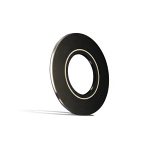
VCS-ID™ Isolating Gaskets/Kits
The VCS-ID® (Inside Diameter) Seal introduces an internal, machined PTFE seal at the bore of the existing VCS design platform. The use of a patented interlocking mechanism ensures an extremely tight seal at the bore and resistance to effects from internal pressure or aggressive media. The interlocking mechanism is intentionally designed to be approximately 0.100” larger than the pipe ID.
During installation/loading, the interlocking mechanism will compress to a final state that is slightly larger than the pipe ID. This reduces cavitation in the piping, reduces flange erosion, and helps prevent microbiologically induced corrosion (MIC), while not affecting any line pigging operations.
Additionally, the PTFE interlocking mechanism creates a longer effective isolating distance than the standard platform. Traditional VCS gaskets leave the steel core exposed to the media. This increases the likelihood of the formation of an electrically conductive bridge between the flange face and steel core of the gasket, especially if the media contains conductive particles that lead to sediment build-up in the pipeline. Because the thickness of the inner PTFE seal is the same as the gasket thickness, the formation of an electrical bridge caused by conductive sediment build-up between the gasket steel core and the flange face is eliminated. Further, PTFE is not hygroscopic, so it does not tend to absorb water, making it even more attractive as a front-line defense in electrical isolation. This unique design helps solve problems where hydro-tested lines may no longer be isolated.
Our patented interlocking mechanism is “dual locking” to provide a secure seal that won’t dislodge during handling, transport, or installation. The “dual locking” feature creates a positive lock in both vertical and radial directions.
The interlocking mechanism also eliminates the need for exotic metal gasket core material because it breaks the metal-to-metal path. Obtaining exotic metals can cause long lead times and extra expenses that are eliminated with the use of a VCS-ID seal.
Another benefit of the VCS-ID seal is that PTFE doesn’t have an affinity for water absorption, installations where electrical isolation testing is performed shortly after the hydro-test are less likely to be corrupted. The VCS-ID does not require any more torque than the standard VCS or VCFS, making installation simple using the same specification charts.
Features & Benefits:
- Ideal for applications that would chemically attack GRE
- Installations where electrical isolation testing is performed shortly after hydro-testing
- Creates larger gap between flanges for better resistance to conductive sediment build-up
- Great for use in high Chloride applications that could cause Stress Corrosion Cracking with a stainless steel core
- Eliminates the need for exotic metal cores that match the exotic metal flange material
- Available with G-11 carrier for 392°F / 200°C
- Dual Seal nominal pipe sizes in 6” and up are standard
- Larger than the pipe bore so that under compression it matches the pipe bore
Applications:
- Flange insulation in conjunction with cathodic protection
- Insulation between dissimilar metals to prevent galvanic corrosion
- Wellhead isolation from interconnected flow lines
- Valve connections
- Christmas Tree connections
- Pump connections
- Compressor connections
- Chemical applications
- Mating mismatched ring-joint to raised-face flanges (VCS will seal in ring-joint, raised-face, and flat face/slip-on flanges)
- Eliminates the fluid trap common to ring-type joint (RTJ) flanges where the potential of stress corrosion cracking exists with corrosive media
- For slip-on flanges
Specification:
One isolating and sealing gasket, VCS-ID Type “F”, 0.260” thick or .308” thick, 316 stainless steel core retainer laminated on both sides with a G-10 fiberglass reinforced laminate containing a patented, mechanically locking PTFE sealing element. The PTFE element will be concave on the I.D. to induce pressure activation. The PTFE sealing element will be approximately 0.100” larger than the bore. Sealing element placement shall accommodate either flat, raised, or RTJ face flanges. The G-10 retainer shall have an 800 volts/mil dielectric strength and a minimum 65,000 psi compressive strength.
Note: Physical, mechanical, and electrical properties are obtained through the testing of material samples in laboratory-controlled environments. Exposure to moisture or elevated temperature will change values.